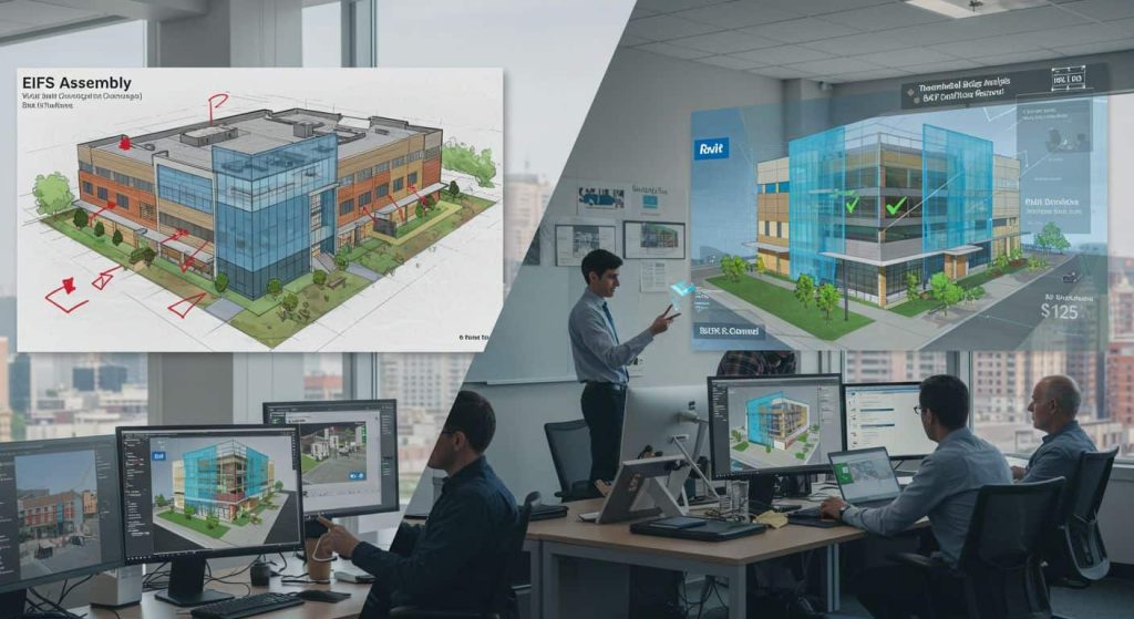
The Future of EIFS Construction Starts with BIM Coordination
The construction industry is changing fast. Building Information Modeling (BIM) has transformed how we design and build structures. When combined with Exterior Insulation and Finish Systems (EIFS), it creates a powerful partnership that eliminates costly mistakes and streamlines the entire building process.
After 22 years in the EIFS business, I’ve seen countless projects struggle with coordination issues. Traditional design methods leave too much room for error. But BIM technology changes everything. It lets architects, engineers, and contractors work together seamlessly before the first wall goes up.
The numbers don’t lie. Projects using BIM see dramatic improvements across every metric that matters. Fewer change orders. Faster installation. Better energy performance. Higher quality results. Most importantly, happier clients who get exactly what they expected.
Key Takeaways:
- BIM reduces EIFS design conflicts by up to 85% through advanced clash detection
- Digital modeling cuts project timelines by 20-30% for complex exterior wall systems
- Integrated workflows improve energy efficiency calculations and LEED certification processes
- Real-time collaboration prevents costly field changes during installation
- Smart material libraries ensure accurate specifications and cost estimates
What Is BIM and Why Does It Matter for EIFS?
Building Information Modeling (BIM) creates a digital twin of your building project. Think of it as a virtual construction site where every component is tested before real construction begins. Unlike traditional CAD drawings that show only basic geometry, BIM models contain rich data about materials, performance, costs, and installation sequences.
For exterior insulation and finish systems, this technology offers incredible advantages. EIFS projects involve multiple layers, complex details, and precise coordination between trades. When even small mistakes can lead to moisture problems or thermal bridges, accuracy becomes critical.
The Traditional Problem: Working in Silos
Without BIM, teams work in isolation. The architect designs the exterior wall assembly using one software package. The structural engineer calculates loads in another program. The mechanical engineer routes HVAC systems without seeing the wall details. The EIFS contractor estimates materials from 2D drawings that may not reflect the final design.
When these separate efforts come together during construction, problems emerge. Common issues include:
- Drainage plane conflicts with structural elements
- Thermal bridge problems at window returns and penetrations
- Clearance clashes between mechanical systems and continuous insulation
- Installation sequence confusion leading to rework and delays
- Moisture management details that don’t account for other building systems
- Specification inconsistencies between different trade drawings
- Cost overruns from unforeseen coordination requirements
I’ve seen projects where the EIFS contractor arrives on site only to discover that the structural steel connections block access to install the drainage cavity. Or where the mechanical engineer’s ductwork runs exactly where the continuous insulation needs to go. These conflicts cost time, money, and often compromise the building’s performance.
The BIM Solution: Integrated Design Process
BIM software like Autodesk Revit creates a shared model where every trade can see potential conflicts before they become real problems. When we design an EIFS assembly in Revit, the system automatically checks for issues and alerts the team to potential problems.
The software identifies several types of conflicts:
- Hard clashes – where two objects occupy the same physical space
- Soft clashes – clearance violations that prevent proper installation
- 4D scheduling conflicts in construction sequencing
- Specification inconsistencies across different building systems
- Performance issues like thermal bridging or moisture problems
This integrated approach transforms how EIFS projects are designed and built. Instead of discovering problems during construction, teams resolve conflicts while changes are still easy and inexpensive to make.
Essential BIM Tools for EIFS Design
Modern EIFS projects rely on several key BIM platforms and specialized tools. Each serves a specific purpose in the design and coordination process:
| Software Platform | Primary Use | EIFS Application | Typical Cost |
|---|---|---|---|
| Autodesk Revit | 3D modeling and documentation | EIFS wall assemblies, material specifications | $2,300/year |
| Navisworks Manage | Clash detection and coordination | Multi-trade conflict resolution | $3,500/year |
| BIMsmith Market | Material libraries | Manufacturer-specific EIFS components | Free |
| BIMobject | Product databases | Downloadable EIFS families and cut sheets | Free |
| SketchUp | Conceptual design | Early-stage EIFS visualization | $299/year |
| Vectorworks | Architectural design | Alternative to Revit for smaller firms | $2,900/year |
| ArchiCAD | Building modeling | European-preferred BIM platform | $3,600/year |
Autodesk Revit: The Industry Standard
Revit dominates the BIM market for good reasons. Its parametric family system perfectly matches how EIFS systems are specified and installed. Each component in the wall assembly becomes a smart object with embedded properties.

Revit excels at:
- Material specification with accurate thermal properties
- Assembly modeling showing layer relationships
- Detail generation for complex connections
- Quantity takeoffs for accurate cost estimates
- Energy analysis integration for sustainable design
- Construction documentation that updates automatically
Navisworks: Coordination and Clash Detection
While Revit handles design, Navisworks Manage coordinates between trades. This software imports models from multiple sources and identifies conflicts automatically. For EIFS projects, Navisworks typically finds 50-100 clashes in a medium-sized commercial building.
The software categorizes clashes by severity:
- Critical – conflicts that prevent installation
- Warning – potential access or clearance issues
- Advisory – minor conflicts that need review
Free BIM Resources: BIMsmith and BIMobject
BIMsmith Market and BIMobject provide vast libraries of manufacturer-specific content. Instead of creating every EIFS component from scratch, designers can download free BIM objects that include accurate specifications.
These platforms offer:
- Complete EIFS assemblies from major manufacturers
- Revit materials with thermal and physical properties
- Installation guides linked to specific products
- Cut sheets and technical documentation
- Specification sections following CSI format
Revit Families for EIFS Components
Parametric families in Revit represent each EIFS layer with precise specifications. A typical exterior insulation and finish assembly includes multiple components that must work together perfectly:
Substrate Layer
The foundation for any EIFS system starts with the substrate:
- Concrete masonry units with specific density ratings
- Steel frame with gypsum sheathing or concrete substrate
- Wood frame construction with appropriate sheathing
- Insulated concrete forms for integrated thermal performance
Each substrate type affects the EIFS design differently. BIM families include connection details, thermal properties, and installation requirements specific to each substrate.
Air and Water-Resistive Barrier
The weather barrier layer provides critical moisture protection:
- Fluid-applied membranes for complex geometries
- Sheet-applied materials for standard applications
- Vapor-permeable options for climate-specific needs
- Self-adhering products for difficult substrates
BIM families specify vapor permeance ratings, application temperatures, and compatibility with adjacent materials.
Continuous Insulation Layer
EPS foam board specifications include multiple parameters:
- Density ratings from 1.0 to 2.0 pounds per cubic foot
- Thickness options from 1 inch to 6 inches
- R-value calculations based on thickness and density
- Compressive strength for structural requirements
- Flame spread ratings for code compliance
Advanced families include thermal bridging calculations at fastener locations and expansion coefficient data for movement joint design.
Base Coat System
The reinforcing mesh and base coat assembly includes:
Mesh Specifications:
- Weight (typically 4.5 to 6.0 oz/sq yd)
- Alkali resistance ratings
- Tensile strength values
- Mesh opening size for proper embedment
Base Coat Options:
- Cementitious base coat for traditional applications
- Acrylic base coat for flexible assemblies
- Polymer-modified systems for enhanced performance
- Impact-resistant formulations for high-traffic areas
Finish Coat Specifications
The final finish coat layer includes extensive customization options:
Texture Varieties:
- Smooth finishes for modern aesthetics
- Sand textures for traditional appearances
- Aggregate finishes for heavy texture
- Custom textures to match existing buildings
Color Systems:
- Through-body coloring for fade resistance
- Integral color systems for cost-effectiveness
- Paint systems for maximum color options
- Special effects finishes for unique appearances
Each finish option includes specifications for application thickness, cure times, and maintenance requirements.
Advanced Clash Detection for EIFS Projects
Clash detection software identifies conflicts before they become expensive field problems. Modern algorithms can process millions of geometric relationships in minutes, finding issues that would take weeks to discover manually.
Types of Clashes in EIFS Design
Hard Clashes: Physical Conflicts These represent the most serious coordination problems:
- Structural beams penetrating the drainage cavity space
- Mechanical equipment conflicting with continuous insulation
- Window frames overlapping expansion joint locations
- Electrical conduits running through insulation layers
- Plumbing penetrations without proper sealing details
Soft Clashes: Access and Clearance Issues Less obvious but equally important coordination problems:
- Insufficient space for mesh embedding around penetrations
- Sealant joint access issues at complex geometry
- Installation sequence conflicts between trades
- Scaffolding interference with adjacent building elements
- Tool access limitations in confined spaces
Clearance Clashes: Installation Constraints Detailed coordination issues that affect quality:
- Backer rod installation space at movement joints
- Access for mechanical fasteners in tight areas
- Adhesive mortar application clearances
- Quality control inspection access
- Temporary protection installation space
Advanced Clash Detection Algorithms
Modern software uses sophisticated algorithms to identify potential problems:
Geometric Analysis:
- Bounding box checks for basic conflicts
- Mesh intersection analysis for complex geometry
- Clearance calculations based on installation requirements
- Tolerance analysis for manufacturing variations
Rule-Based Detection:
- Code compliance checking against building standards
- Manufacturer specifications verification
- Installation sequence logic validation
- Performance criteria verification

Temporal Analysis:
- 4D scheduling conflict identification
- Construction sequence optimization
- Weather window planning integration
- Material delivery coordination
Clash Detection
Clash Detection Impact Statistics
Clash Types Distribution
Comprehensive BIM Content Libraries
BIM content libraries have revolutionized EIFS design by providing accurate, manufacturer-specific components that designers can download and use immediately. These libraries eliminate guesswork and ensure specifications match real products.
Major EIFS Manufacturer Libraries
Dryvit Systems Libraries:
- Complete Outsulation assemblies with performance data
- Barrier EIFS and drainage EIFS options
- Textured finishes with accurate appearance properties
- Special application details for complex projects
- Installation guides integrated with BIM objects
Sto Corp Product Families:
- StoTherm continuous insulation systems
- Drainage cavity details with performance specifications
- Color matching tools integrated with design software
- Sustainability data for LEED calculations
- Quality assurance protocols embedded in families
BASF Insulation Libraries:
- Neopor expanded polystyrene specifications
- Thermal performance data across temperature ranges
- Moisture resistance properties for humid climates
- Fire performance ratings for code compliance
- Dimensional stability data for movement calculations
Creating Custom EIFS Families
When manufacturer families don’t exist, custom parametric families ensure accuracy and consistency across projects:
Family Parameter Structure:
Custom EIFS Family Parameters
Parametric Design Structure for BIM Implementation
Geometric Parameters
- Wall Height Variable
- Insulation Thickness
- Base Coat Thickness
- Finish Thickness 1/32″ to 1/16″
Material Parameters
- EPS Density
- Base Coat Type
- Mesh Weight
- Finish Texture
Performance Parameters
- R-Value Calculated from thickness/density
- U-Value Including thermal bridging
- Vapor Permeance Climate-specific
- Fire Rating Per ASTM E119
Visual Parameters
- Color Selection RGB values
- Texture Pattern
- Reflectance Values For energy analysis
- Surface Roughness For weathering analysis
Advanced Family Features:
- Nested families for complex assemblies
- Conditional visibility based on application type
- Automatic scheduling for quantity takeoffs
- Cost data integration for budget tracking
- Specification text generation
Cloud-Based Library Management
Modern BIM workflows rely on cloud-based libraries that provide:
Real-Time Updates:
- Manufacturer product changes automatically reflected
- Code compliance updates pushed to all users
- Installation guide revisions distributed immediately
- Performance data corrections applied retroactively
Collaboration Features:
- Shared libraries across project teams
- Version control for custom families
- Access permissions for proprietary content
- Usage tracking for licensing compliance
Quality Assurance:
- Automated testing of family geometry
- Performance verification against standards
- Compatibility checking across software versions
- Documentation completeness validation
Energy Modeling Integration with BIM
BIM software connects directly to energy analysis tools, making sustainable building design more precise and reliable. This integration eliminates manual data transfer errors and ensures analysis reflects the actual building design.
Thermal Performance Analysis Through BIM
EIFS provides excellent continuous insulation, but BIM helps optimize the design by analyzing the complete thermal envelope:

Comprehensive R-Value Calculations:
- Effective R-value across the entire wall assembly
- Thermal bridge impact at structural connections
- Fastener thermal bridging calculations
- Air leakage effects on thermal performance
- Moisture impact on insulation effectiveness
Advanced U-Value Analysis:
- Overall wall thermal transmittance calculations
- Code compliance verification against local requirements
- Energy code optimization for different climate zones
- LEED credit qualification documentation
- Utility rebate program compliance verification
Dew Point Analysis:
- Condensation risk assessment throughout wall assembly
- Vapor drive calculations for different seasons
- Moisture accumulation potential at interfaces
- Material selection optimization for hygrothermal performance
Energy Modeling Software Integration
EnergyPlus Integration:
- Direct model transfer from Revit to EnergyPlus
- HVAC system sizing based on actual building loads
- Annual energy consumption predictions
- Peak demand calculations for utility planning
- Carbon footprint analysis for sustainability reporting
eQUEST Connectivity:
- Building geometry transfer with thermal zones
- Material properties automatically populated
- Lighting and equipment loads coordination
- HVAC system performance modeling
- Economic analysis of energy efficiency measures
IES VE Integration:
- Dynamic thermal modeling with weather data
- Daylight analysis coordination with EIFS design
- Computational fluid dynamics for complex geometries
- Solar gain calculations through wall assemblies
- Overheating risk assessment for different orientations
Green Building Rating System Support
LEED v4.1 Credit Support:
- EA Credit 2 (Optimize Energy Performance) documentation
- MR Credit 2 (Building Product Disclosure) tracking
- EA Credit 1 (Enhanced Commissioning) coordination
- IEQ Credit 1 (Enhanced Indoor Air Quality) verification
Green Globes Integration:
- Energy efficiency pathway documentation
- Resource conservation credit tracking
- Indoor environmental quality verification
- Life cycle assessment data compilation
BREEAM Compliance:
- Energy performance standard verification
- Materials sourcing documentation
- Thermal comfort analysis coordination
- Pollution prevention strategy implementation
Lifecycle Assessment Through BIM
BIM models support comprehensive lifecycle assessment by tracking environmental impacts throughout the building’s life:
Embodied Carbon Analysis:
- Material production carbon footprint calculation
- Transportation impact assessment
- Installation process energy consumption
- Maintenance activity carbon accounting
- End-of-life disposal or recycling impacts
Operational Carbon Tracking:
- Energy consumption monitoring integration
- HVAC system efficiency verification
- Building performance optimization opportunities
- Renewable energy integration potential
- Carbon offset program coordination
Water Impact Assessment:
- Stormwater management system integration
- Rainwater harvesting potential with EIFS design
- Irrigation reduction through efficient envelope design
- Water quality protection through proper drainage
Advanced BIM Execution Planning
Successful BIM implementation requires comprehensive planning and clear coordination protocols. The BIM Execution Plan serves as the roadmap for how teams will use technology throughout the project.
Level of Development (LOD) Standards for EIFS
LOD 100 – Conceptual:
- Basic EIFS assembly representation
- Approximate geometry for massing studies
- General performance assumptions
- Cost estimating at assemblies level

LOD 200 – Schematic Design:
- System type selection (barrier vs. drainage)
- Insulation thickness determination
- Basic details at major transitions
- Energy modeling input development
LOD 300 – Design Development:
- EIFS assembly configuration fully defined
- Major component sizing established
- Installation sequence documented
- Coordination requirements identified
- Specification sections outlined
LOD 350 – Construction Documentation:
- Expansion joint locations finalized
- Sealant joint details completed
- Mechanical fastener specifications confirmed
- Quality control requirements defined
- Submittal requirements documented
LOD 400 – Fabrication and Installation:
- Cut sheet accuracy verified
- Shop drawing coordination completed
- Material procurement specifications finalized
- Installation procedures detailed
- Quality assurance protocols established
LOD 500 – As-Built Verification:
- Actual installation conditions documented
- Performance testing results integrated
- Maintenance procedures finalized
- Warranty information compiled
- Operations manual coordination
Model Coordination Workflow
Weekly Coordination Meetings: The foundation of successful BIM coordination involves structured, regular communication:
Meeting Agenda Structure:
- Clash detection report review from all participating trades
- Design changes discussion and impact assessment
- Installation sequence updates and optimization
- Issue tracking status and resolution planning
- Quality control checkpoint reviews
- Schedule coordination and milestone verification
Participant Responsibilities:
Architect:
- Design intent clarification and updates
- Aesthetic coordination with building systems
- Code compliance verification and documentation
- Client communication regarding design changes
Structural Engineer:
- Connection details coordination with EIFS attachment
- Load path verification through wall assemblies
- Expansion joint location optimization
- Seismic design integration with exterior walls
MEP Engineers:
- Penetration coordination with drainage planes
- Thermal bridging minimization at connections
- Equipment access coordination with wall systems
- Fire stopping details coordination
EIFS Contractor:
- Installation sequence optimization and scheduling
- Material coordination and procurement planning
- Quality control procedure development
- Field coordination requirements identification
Issue Tracking and Resolution
Digital Issue Management: Modern BIM platforms include sophisticated issue tracking capabilities that link problems directly to 3D model locations:
Issue Categories:
- Design conflicts requiring architectural resolution
- Coordination issues between multiple trades
- Code compliance questions needing authority review
- Performance concerns requiring analysis or testing
- Cost implications requiring value engineering
- Schedule impacts requiring timeline adjustment
Resolution Workflow:
- Issue identification through clash detection or design review
- Impact assessment on cost, schedule, and performance
- Alternative development with stakeholder input
- Decision documentation with approval tracking
- Implementation verification through model updates
- Quality assurance confirmation of resolution
Point Cloud Integration and Reality Capture
Reality capture technology creates accurate as-built models for retrofit projects and renovation work. This capability is particularly valuable for EIFS applications on existing buildings where precise measurements are critical.
Scan to BIM Workflow
Point Cloud Acquisition:
- Terrestrial laser scanning for building exteriors
- Drone-based scanning for large or tall structures
- Handheld scanners for detailed areas
- Photogrammetry for texture and color capture
Data Processing:
- Point cloud registration to coordinate systems
- Noise filtering and data cleanup
- Surface mesh generation from point data
- Texture mapping for realistic visualization
BIM Model Development:
- Geometric modeling from point cloud data
- As-built conditions documentation
- Existing system assessment and analysis
- New design integration with existing conditions
Applications for EIFS Retrofit Projects
Existing Building Assessment: Point cloud scanning reveals conditions that traditional measuring cannot detect:
- Wall surface irregularities affecting EIFS installation
- Structural movement that impacts expansion joint placement
- Existing penetrations requiring special sealing details
- Architectural features needing custom EIFS solutions
Design Integration:
- Accurate measurements eliminate field surprises
- Existing conditions modeling supports design decisions
- Interference detection with existing building systems
- Cost estimation accuracy improves significantly
Quality Control:
- Installation verification against design intent
- Dimensional accuracy confirmation during construction
- Progress monitoring through periodic scanning
- Final documentation for maintenance and warranty
Case Study: Historic Building EIFS Retrofit
A recent project involving historic preservation in downtown Indianapolis demonstrated the value of scan to BIM technology:
Project Challenges:
- Masonry walls with significant irregularities
- Historic details requiring precise replication
- Unknown conditions behind existing facades
- Code compliance requirements for modern performance
Point Cloud Solutions:
- Millimeter accuracy measurements of existing conditions
- 3D documentation of historic architectural features
- Hidden condition discovery through non-destructive scanning
- Design verification before construction begins
Results:
- Construction timeline reduced by 3 weeks
- Field changes eliminated through accurate modeling
- Cost savings of $85,000 from eliminated rework
- Historic accuracy maintained through precise documentation
4D Scheduling and Construction Sequencing
4D BIM links the 3D model to project schedules, creating powerful visualizations that show exactly how construction will proceed. For EIFS projects, this capability prevents conflicts and optimizes installation sequences.
Construction Sequencing Optimization
EIFS Installation Phases: Traditional installation follows a logical sequence, but 4D modeling helps optimize timing and coordination:
Phase 1: Substrate Preparation
- Surface cleaning and preparation
- Structural repairs completion
- Penetration coordination with other trades
- Quality verification before EIFS application
Phase 2: Weather Barrier Installation
- Air and water-resistive barrier application
- Sealing coordination with window installation
- Penetration flashing integration
- Quality testing and verification
Phase 3: Insulation Installation
- Continuous insulation placement and fastening
- Thermal bridge mitigation at connections
- Expansion joint preparation
- Installation quality verification
Phase 4: Base Coat Application
- Mesh installation and embedding
- Base coat application and curing
- Surface preparation for finish application
- Quality control testing and approval
Phase 5: Finish Application
- Finish coat application and texture creation
- Color verification and touch-up
- Final quality inspection and approval
- Protection installation during adjacent work
Weather Window Planning
Climate Considerations: EIFS installation requires specific weather conditions, and 4D scheduling helps plan around Indiana’s variable climate:
Temperature Requirements:
- Application temperatures between 40°F and 90°F
- Surface temperatures verification before application
- Ambient conditions monitoring during curing
- Frost protection during winter installations
Moisture Limitations:
- Precipitation forecasts integrated with schedule
- Humidity control during application and curing
- Wind speed limitations for finish application
- Dew point considerations for early morning work
Seasonal Planning:
- Spring installation windows after freeze risk
- Summer heat management for material performance
- Fall completion before winter weather
- Winter protection strategies for ongoing work
Critical Path Integration
4D BIM identifies how EIFS installation affects other building systems and overall project completion:
Dependent Activities:
- Window installation must precede EIFS flashing
- Roofing completion required before wall system start
- Structural work completion before insulation installation
- MEP rough-in coordination with penetration sealing
Parallel Activities:
- Interior framing while exterior walls cure
- Site utilities installation during wall preparation
- Landscape preparation while building envelope completes
- Final inspections coordination with building systems
Mobile BIM Applications and Field Technology
Mobile BIM applications have revolutionized how field teams access and use design information. Tablets and smartphones now provide real-time access to 3D models, installation details, and quality control procedures.
Field-Accessible BIM Platforms
Autodesk BIM 360:
- Model viewing with markup capabilities
- Issue tracking linked to 3D locations
- Progress photos tied to model elements
- Quality control checklists with model references
- Document access including specifications and submittals
Procore Integration:
- Project management coordination with BIM data
- Daily reports linked to model progress
- Material tracking with delivery coordination
- Safety management tied to work locations
- Change order management with visual references
PlanGrid Capabilities:
- Drawing comparison between versions
- Field markup synchronization across teams
- Progress tracking with photo documentation
- Punch list management with location data
- Offline access for areas with poor connectivity
Quality Control Through Mobile BIM
Installation Verification: Field teams use mobile devices to verify that installation matches design intent:
Dimensional Verification:
- Measurement tools integrated with model geometry
- Layout confirmation using AR capabilities
- Tolerance checking against specification requirements
- Photo documentation with model overlay verification
Material Confirmation:
- Barcode scanning for material verification
- Specification checking against approved submittals
- Installation procedure access with step-by-step guidance
- Quality standards reference with acceptance criteria
Progress Documentation:
- Daily progress photos tied to model elements
- Completion tracking with percentage calculations
- Issue identification with immediate notification
- Weather condition documentation for warranty purposes
Augmented Reality (AR) Integration
AR-Enhanced Installation: Emerging augmented reality technology overlays digital information onto real-world views:
Installation Guidance:
- Layout lines projected onto building surfaces
- Component placement verification through AR
- Installation sequence visualization in real environment
- Quality criteria display during application
Inspection Support:
- Design comparison with as-built conditions
- Problem identification through model overlay
- Measurement verification using AR tools
- Documentation enhancement with contextual information
Cost Benefits and ROI Analysis
The financial advantages of BIM implementation for EIFS projects are substantial and measurable. While initial software and training costs require investment, returns typically appear within the first major project.
Direct Cost Savings Analysis
BIM Cost Savings Analysis
Comprehensive Financial Impact Assessment
Design Phase Savings
| Cost Category | Traditional Method | BIM Method | Potential Savings |
|---|---|---|---|
| Design Changes | $8,000 average per project | $1,200 average per project | 85% reduction |
| Coordination Time | 120 hours typical | 45 hours typical | 62% reduction |
| Rework Design | $15,000 average | $3,000 average | 80% reduction |
| Specification Errors | $5,000 typical cost | $500 typical cost | 90% reduction |
Construction Phase Savings
| Impact Area | Traditional Approach | BIM Approach | Savings Realized |
|---|---|---|---|
| Material Waste | 15-20% excess ordering | 5-8% excess ordering | 60% waste reduction |
| Field Changes | $12,000 typical cost | $2,500 typical cost | 80% reduction |
| Schedule Delays | 3-4 weeks average | 0.5-1 week average | 75% time reduction |
| Quality Issues | $8,000 rework average | $1,500 rework average | 81% reduction |
Long-Term Operational Benefits
| Performance Metric | Traditional Design | BIM-Optimized Design | Improvement |
|---|---|---|---|
| Energy Efficiency | 15-20% over code minimum | 25-35% over code minimum | 65% better performance |
| Maintenance Costs | $0.45/sq ft annually | $0.28/sq ft annually | 38% cost reduction |
| Warranty Claims | 12% of projects | 4% of projects | 67% claim reduction |
| Client Satisfaction | 78% highly satisfied | 94% highly satisfied | 20% improvement |
Project Size Impact on ROI
Small Projects (Under 10,000 sq ft):
- BIM Investment: $8,000 – $12,000
- Cost Savings: $15,000 – $25,000
- ROI Timeline: 6-9 months
- Primary Benefits: Reduced field changes, better coordination
Medium Projects (10,000 – 50,000 sq ft):
- BIM Investment: $15,000 – $25,000
- Cost Savings: $45,000 – $75,000
- ROI Timeline: 3-6 months
- Primary Benefits: Major clash prevention, schedule optimization
Large Projects (Over 50,000 sq ft):
- BIM Investment: $25,000 – $45,000
- Cost Savings: $125,000 – $200,000
- ROI Timeline: 2-4 months
- Primary Benefits: Comprehensive coordination, energy optimization
ROI Analysis by Project Size
- BIM Investment $8K – $12K
- Cost Savings $15K – $25K
- Net Benefit $7K – $13K
- BIM Investment $15K – $25K
- Cost Savings $45K – $75K
- Net Benefit $30K – $50K
- BIM Investment $25K – $45K
- Cost Savings $125K – $200K
- Net Benefit $100K – $155K
Competitive Advantage Through BIM
Market Differentiation: Contractors using BIM gain significant competitive advantages:
Proposal Advantages:
- Detailed visualization helps clients understand scope
- Accurate cost estimates from precise quantity takeoffs
- Risk mitigation through clash detection demonstrations
- Professional presentation with 3D walkthroughs
- Value engineering opportunities clearly illustrated
Client Confidence Factors:
- Proven track record with technology adoption
- Transparent process with regular model updates
- Quality assurance through digital verification
- Problem prevention rather than reaction
- Future-ready approach for building operations
Sustainable Design Enhancement Through BIM
BIM technology amplifies the environmental benefits of EIFS through more precise design optimization and better performance prediction. The integration enables designers to maximize sustainability while maintaining cost-effectiveness.
Advanced Energy Analysis Capabilities
Whole Building Energy Modeling: BIM platforms connect seamlessly with sophisticated energy analysis tools that evaluate building performance under real operating conditions:
Annual Energy Simulations:
- 8,760-hour analysis using local weather data
- Dynamic thermal modeling accounting for thermal mass
- HVAC system interaction with envelope performance
- Daylighting integration affecting electric lighting loads
- Occupancy patterns impact on energy consumption
Peak Load Calculations:
- Design day analysis for equipment sizing
- Utility demand optimization for cost reduction
- Grid interaction planning for renewable integration
- Energy storage system coordination with building loads
- Smart grid compatibility for demand response programs
Carbon Footprint Analysis:
- Operational carbon from energy consumption
- Embodied carbon from material production
- Transportation impacts from material sourcing
- Construction phase energy consumption
- End-of-life disposal or recycling impacts
LEED Optimization Through BIM
Enhanced Energy Performance (EA Credit 1): BIM enables precise energy modeling that supports high-performance design:
Performance Thresholds:
- 10% improvement: 1-3 LEED points
- 20% improvement: 4-6 LEED points
- 30% improvement: 7-9 LEED points
- 40% improvement: 10-12 LEED points
- 50% improvement: 13-18 LEED points
EIFS Contribution to Performance:
- Continuous insulation eliminates thermal bridging
- Air barrier integration reduces infiltration loads
- Thermal mass benefits from interior mass exposure
- Solar heat gain control through finish selection
- Moisture management prevents insulation degradation
Materials and Resources Credits: BIM supports comprehensive material tracking for various LEED credits:
Environmental Product Declarations (MR Credit 1):
- 20% compliance: 1 LEED point
- 40% compliance: 2 LEED points
- Material cost tracking through BIM quantity takeoffs
- Manufacturer EPD integration with BIM libraries
- Supply chain transparency documentation
Sourcing of Raw Materials (MR Credit 2):
- 25% regional materials: 1 LEED point
- 50% regional materials: 2 LEED points
- Geographic tracking of material sources
- Transportation distance calculations
- Local economic impact documentation
Green Building Rating System Integration
BREEAM Optimization: BIM supports BREEAM assessment through detailed performance documentation:
Energy Performance Standards:
- Building envelope performance verification
- Thermal bridging minimization strategies
- Air tightness achievement through proper details
- Energy monitoring system integration planning
- Renewable energy coordination with building systems
Material Sourcing and Impact:
- Life cycle assessment data integration
- Responsible sourcing certification tracking
- Waste minimization through accurate quantity takeoffs
- Material health impact assessment
- Regional material preference documentation
Green Globes Coordination: BIM facilitates Green Globes compliance through comprehensive project documentation:
Assessment Areas:
- Energy performance pathway optimization (35% weight)
- Indoor environment quality verification (15% weight)
- Site management integration (10% weight)
- Water conservation strategy coordination (10% weight)
- Resource and material use optimization (15% weight)
- Emissions and waste minimization (15% weight)
Advanced Sustainability Analysis
Life Cycle Assessment Integration: BIM platforms increasingly connect with LCA software for comprehensive environmental impact assessment:
Impact Categories Analyzed:
- Global warming potential (carbon footprint)
- Ozone depletion potential from refrigerants
- Acidification from material production
- Eutrophication from manufacturing processes
- Resource depletion of non-renewable materials
- Human health impacts from material toxicity
Temporal Analysis:
- Construction phase environmental impacts
- Operational phase energy and water consumption
- Maintenance phase material replacement impacts
- End-of-life disposal or recycling benefits
- 50-year lifecycle comprehensive assessment
Optimization Opportunities:
- Material substitution based on impact analysis
- Design modifications to improve performance
- Regional sourcing to reduce transportation impacts
- Renewable energy integration optimization
- Waste reduction through precise material planning
Advanced Training and Implementation Strategies
Successful BIM adoption requires comprehensive training programs and systematic implementation approaches. Organizations that invest properly in training see faster returns and higher success rates.
Comprehensive Training Program Development
BIM Training Requirements by Role
- Revit fundamentals and EIFS-specific families
- Parametric design techniques for complex geometries
- Energy modeling integration and optimization
- Code compliance verification through BIM
- Presentation techniques for client communication
- Quality assurance procedures for design accuracy
- Model coordination with architectural designs
- Structural integration with EIFS systems
- MEP coordination and clash detection
- Performance analysis and verification
- Code compliance checking and documentation
- Construction administration through BIM
- Model interpretation and field coordination
- Mobile BIM applications and field technology
- Quality control procedures using digital tools
- Progress tracking and documentation methods
- Issue identification and resolution workflows
- Safety management through model coordination
- BIM execution planning and team coordination
- Clash detection interpretation and resolution
- Schedule integration with 4D modeling
- Cost management through quantity takeoffs
- Client communication and expectation management
- Performance measurement and continuous improvement
Role-Specific Training Curricula:
Architects and Designers (80-120 hours):
- Revit fundamentals and EIFS-specific families
- Parametric design techniques for complex geometries
- Energy modeling integration and optimization
- Code compliance verification through BIM
- Presentation techniques for client communication
- Quality assurance procedures for design accuracy
Training Schedule:
- Week 1-2: Basic Revit skills and interface
- Week 3-4: EIFS family creation and modification
- Week 5-6: Energy analysis and sustainability tools
- Week 7-8: Advanced modeling and coordination
- Week 9-10: Project workflow and quality control
- Week 11-12: Client presentation and communication
Engineers (60-80 hours):
- Model coordination with architectural designs
- Structural integration with EIFS systems
- MEP coordination and clash detection
- Performance analysis and verification
- Code compliance checking and documentation
- Construction administration through BIM
Contractors and Field Personnel (40-60 hours):
- Model interpretation and field coordination
- Mobile BIM applications and field technology
- Quality control procedures using digital tools
- Progress tracking and documentation methods
- Issue identification and resolution workflows
- Safety management through model coordination
Project Managers (60-80 hours):
- BIM execution planning and team coordination
- Clash detection interpretation and resolution
- Schedule integration with 4D modeling
- Cost management through quantity takeoffs
- Client communication and expectation management
- Performance measurement and continuous improvement
Implementation Methodology
BIM Implementation Timeline
Phase 1: Pilot Project Selection (Months 1-2) Choose appropriate projects for initial BIM implementation:
Ideal Pilot Project Characteristics:
- Medium complexity (10,000-30,000 sq ft)
- Supportive client willing to embrace new processes
- Experienced team with some BIM familiarity
- Adequate timeline for learning curve accommodation
- Clear success metrics for performance evaluation
Phase 2: Team Preparation (Months 2-4)
- Software procurement and installation
- Initial training completion for core team
- Process development and documentation
- Quality standards establishment
- Communication protocols definition
Phase 3: Pilot Execution (Months 4-8)
- Daily coordination with enhanced communication
- Weekly progress assessment and adjustment
- Issue tracking and resolution documentation
- Performance measurement against traditional methods
- Lesson learned compilation for future projects
Phase 4: Process Refinement (Months 8-10)
- Workflow optimization based on pilot experience
- Training enhancement for identified gaps
- Technology upgrades and capability expansion
- Standard development for consistent application
- Success story development for marketing
Phase 5: Full Implementation (Months 10+)
- Company-wide adoption with mandatory standards
- Advanced training for specialized applications
- Continuous improvement through regular assessment
- Innovation integration with emerging technologies
- Industry leadership through best practice sharing
Change Management Strategies
Addressing Resistance to Technology: Organizations often encounter resistance when implementing new technologies:
Common Concerns:
- Learning curve intimidation and time investment
- Cost implications of software and training
- Workflow disruption during transition period
- Technology reliability and system stability
- Client acceptance of new processes
Mitigation Strategies:
- Champion identification within each department
- Success demonstration through small wins
- Gradual implementation rather than sudden change
- Support system development for ongoing assistance
- Incentive programs for early adopters
Cultural Transformation: BIM adoption requires fundamental changes in how teams work:
From Individual to Collaborative:
- Shared models replace isolated drawings
- Real-time coordination replaces periodic meetings
- Transparent communication replaces information hoarding
- Problem prevention replaces reactive troubleshooting
- Quality focus replaces speed emphasis
Quality Assurance and Control Through BIM
Digital quality control transforms how EIFS projects maintain standards throughout design and construction. BIM platforms provide automated checking capabilities that catch problems before they impact project outcomes.
Automated Quality Checking
Model Validation Tools: Modern BIM software includes sophisticated quality assurance capabilities:
Geometric Validation:
- Self-intersection detection in complex surfaces
- Gap identification between adjacent components
- Overlap verification for proper assembly relationships
- Dimension accuracy checking against standards
- Scale factor verification across model elements
Specification Compliance:
- Material property verification against specifications
- Component sizing validation against manufacturer limits
- Installation clearance checking for field access
- Code compliance verification against local requirements
- Performance criteria validation for energy and structural requirements
Coordination Verification:
- Interface checking between different building systems
- Level coordination across multiple trades
- Reference alignment verification for accuracy
- Version control confirmation across team members
- Data consistency checking between model and documents
Performance-Based Quality Metrics
Energy Performance Verification: BIM enables continuous performance monitoring throughout design development:
Thermal Performance Tracking:
- R-value verification across all wall assemblies
- Thermal bridging quantification and minimization
- Air leakage assessment and optimization
- Moisture management verification through hygrothermal analysis
- Dew point calculations for condensation prevention
Quality Benchmarks:
- Energy consumption targets vs. actual predictions
- HVAC sizing optimization through load calculations
- Peak demand management for utility coordination
- Renewable energy integration optimization
- Grid interaction planning for smart building features
Construction Quality Control
Field Verification Protocols: BIM models serve as the quality standard for field installation:
Dimensional Accuracy:
- Layout verification using total station coordination
- Surface flatness checking against tolerance specifications
- Joint spacing verification for expansion requirements
- Penetration location accuracy for proper sealing
- Finish thickness confirmation through sampling
Material Quality Assurance:
- Product identification verification against approved submittals
- Installation sequence confirmation against specifications
- Environmental conditions monitoring during application
- Cure time verification before subsequent operations
- Testing coordination for performance verification
Documentation Requirements:
- Progress photography tied to model elements
- Quality test results linked to specific locations
- Issue identification with immediate notification systems
- Correction verification through follow-up inspection
- Warranty documentation compilation for building owners
Regional Considerations for Central Indiana
Indiana’s climate and building conditions create specific challenges that BIM helps address more effectively than traditional design methods.
Climate-Specific Design Optimization
Indiana Weather Patterns: BIM energy modeling uses actual Indianapolis weather data for accurate performance predictions:
Temperature Extremes:
- Winter design temperatures averaging 5°F
- Summer design temperatures reaching 90°F
- Daily temperature swings affecting thermal stress
- Freeze-thaw cycles impacting material durability
- Seasonal humidity variations affecting moisture management
Precipitation Management:
- Annual rainfall averaging 40 inches requires robust drainage
- Snow loading considerations for structural integration
- Ice formation prevention at vulnerable details
- Wind-driven rain protection through proper drainage planes
- Storm intensity planning for extreme weather events
Indiana Climate Zone 5A Requirements
Energy Code Compliance: Indiana Energy Code requirements are automatically verified through BIM:
Climate Zone 5A Requirements:
- Continuous insulation R-7.5 minimum for steel frame
- Continuous insulation R-5 minimum for mass walls
- Air barrier continuous throughout building envelope
- Thermal bridging mitigation at structural connections
- Window performance coordination with wall systems
Local Building Code Integration
Indiana Building Code Compliance: BIM platforms include automated checking for local code requirements:
Fire Safety Requirements:
- Fire resistance ratings for wall assemblies
- Flame spread index verification for finish materials
- Smoke development index compliance checking
- Fire stopping coordination at penetrations
- Emergency egress coordination with building layout
Structural Integration:
- Wind load resistance for Indiana wind zones
- Seismic design considerations for moderate risk zones
- Foundation coordination with typical Indiana soil conditions
- Expansion joint planning for seasonal movement
- Connection details for structural attachment
Regional Material Sourcing
Local Supply Chain Integration: BIM helps optimize material sourcing from regional suppliers:
Regional Manufacturer Coordination:
- Local EIFS manufacturers with shorter delivery times
- Regional insulation suppliers for cost optimization
- Indiana-based sealant and adhesive suppliers
- Transportation cost optimization through geographic analysis
- Environmental impact reduction through local sourcing
Quality Assurance:
- Approved supplier verification through BIM libraries
- Material testing coordination with local laboratories
- Installation training with regional manufacturer support
- Warranty coordination with local service networks
- Maintenance support through established regional relationships
Working with Indiana Wall Systems’ BIM Capabilities
When you choose Indiana Wall Systems for your EIFS project, you gain access to our comprehensive BIM expertise and digital design capabilities that set us apart in the Central Indiana market.
Our BIM Service Offerings
Pre-Design Consultation: We work with your design team from the earliest project phases:
- Feasibility analysis using preliminary BIM models
- Cost estimation through accurate quantity takeoffs
- Performance prediction using energy modeling integration
- Code compliance verification for local requirements
- Value engineering opportunities identification
Design Development Support: Our team provides comprehensive BIM coordination services:
- 3D modeling of complex EIFS assemblies
- Clash detection coordination with all building trades
- Energy analysis integration for optimal performance
- Construction sequencing optimization for efficiency
- Quality control planning through digital verification
Construction Administration: We use BIM throughout the construction process:
- Field coordination using mobile BIM applications
- Progress tracking with 4D schedule integration
- Quality verification through digital model comparison
- Issue resolution with visual model communication
- Change management through model-based documentation
Technology Investment and Capabilities
Software Platform Expertise: Our team maintains proficiency across multiple BIM platforms:
Primary Platforms:
- Autodesk Revit for comprehensive EIFS modeling
- Navisworks Manage for multi-trade coordination
- BIM 360 for cloud-based team collaboration
- Mobile applications for field team connectivity
- Energy analysis tools for performance optimization
Hardware Infrastructure:
- High-performance workstations for complex model processing
- Mobile devices for field team access
- Cloud storage for secure model sharing
- Backup systems for data protection
- Network infrastructure for seamless collaboration
Training and Development: Our team maintains current expertise through:
- Annual software training and certification updates
- Industry conference participation for best practice learning
- Manufacturer training on new products and technologies
- Continuing education in sustainable design practices
- Technology evaluation for emerging capabilities
Project Success Stories
Case Study: Major Indianapolis Medical Center A 200,000 square foot medical facility project demonstrated our BIM capabilities:
Project Challenges:
- Complex geometry with multiple building connections
- Infection control requirements affecting installation sequences
- Tight schedule with multiple trades working simultaneously
- High performance requirements for energy efficiency
- Historic context requiring architectural sensitivity
BIM Solutions:
- Comprehensive coordination prevented 127 potential conflicts
- 4D scheduling optimized installation sequences
- Energy modeling achieved 35% better than code performance
- Quality control eliminated field rework
- Documentation supported LEED Gold certification
Results:
- Schedule acceleration by 3 weeks through coordination
- Cost savings of $180,000 through conflict prevention
- Energy performance exceeding design targets by 12%
- Client satisfaction leading to additional project awards
- Industry recognition for innovation and quality
Competitive Advantages
Technology Leadership: Our BIM capabilities provide significant advantages:
Design Phase Benefits:
- Early problem identification prevents costly changes
- Accurate cost estimation eliminates budget surprises
- Performance optimization ensures long-term value
- Quality assurance through digital verification
- Client communication enhancement through visualization
Construction Phase Benefits:
- Conflict prevention through comprehensive coordination
- Installation optimization for maximum efficiency
- Quality control through digital standards
- Progress transparency for stakeholder confidence
- Issue resolution speed through visual communication
Long-Term Value:
- Building performance optimization for operational efficiency
- Maintenance planning through comprehensive documentation
- Future renovation support through accurate as-built models
- Warranty support through detailed installation records
- Operational efficiency through smart building integration
Future Innovations in BIM and EIFS
The integration of BIM technology with EIFS continues to evolve rapidly. Emerging technologies promise even greater capabilities for design optimization, construction efficiency, and building performance.
Artificial Intelligence Integration
AI-Powered Design Optimization: Machine learning algorithms are beginning to optimize EIFS design automatically:
Performance Optimization:
- Energy efficiency maximization through AI analysis
- Cost optimization balancing performance and budget
- Material selection based on regional climate data
- Installation sequence optimization for minimum time
- Quality prediction based on historical project data
Automated Design Generation:
- Parametric design optimization for multiple objectives
- Code compliance checking with automatic corrections
- Clash detection with suggested resolution strategies
- Schedule optimization considering weather and resources
- Cost estimation with real-time market pricing
Advanced Reality Technologies
Virtual Reality (VR) Design Review: Immersive technologies enhance design communication and quality:
Client Engagement:
- Design walkthroughs before construction begins
- Material selection visualization in realistic environments
- Performance demonstration through virtual environments
- Cost impact visualization for decision support
- Change evaluation through instant model updates
Training Applications:
- Installation technique training in safe virtual environments
- Safety procedure practice without real-world risks
- Quality standard training with interactive feedback
- Problem solving skill development through simulation
- Team coordination practice for complex projects
Augmented Reality (AR) Field Support: AR technology overlays digital information onto real construction environments:
Installation Guidance:
- Layout projection directly onto building surfaces
- Component identification through visual recognition
- Quality checking with real-time model comparison
- Progress tracking through automatic recognition
- Training support with contextual information display
Internet of Things (IoT) Integration
Smart Building Envelope: EIFS systems increasingly incorporate sensors and monitoring capabilities:
Performance Monitoring:
- Temperature sensors throughout wall assemblies
- Moisture detection at critical interface locations
- Air leakage monitoring through pressure measurements
- Thermal imaging integration for continuous assessment
- Energy consumption tracking for performance verification
Predictive Maintenance:
- Condition monitoring for early problem detection
- Performance degradation prediction through data analysis
- Maintenance scheduling optimization based on actual conditions
- Warranty validation through continuous monitoring
- Life cycle cost optimization through data-driven decisions
3D Printing and Prefabrication
Advanced Manufacturing Integration: BIM models increasingly drive automated manufacturing processes:
Component Prefabrication:
- Custom EIFS components manufactured from BIM data
- Quality control through automated manufacturing
- Installation speed improvement through prefabrication
- Waste reduction through precise manufacturing
- Cost optimization through factory efficiency
On-Site 3D Printing:
- Complex geometries created through additive manufacturing
- Custom details printed for unique applications
- Rapid prototyping for design verification
- Material optimization through advanced printing materials
- Installation integration with traditional construction methods
Conclusion and Next Steps
BIM and EIFS integration represents the future of smart building design and construction. The technology delivers measurable improvements in quality, speed, cost-effectiveness, and building performance that traditional methods simply cannot match.
The Transformation Impact
The construction industry is experiencing a fundamental transformation. Projects that embrace digital design workflows consistently outperform traditional approaches across every metric that matters:
Quality Improvements:
- Design accuracy through comprehensive modeling
- Construction quality through digital verification
- Performance achievement through optimization tools
- Client satisfaction through transparent communication
- Long-term durability through proper design integration
Efficiency Gains:
- Design time reduction through automated processes
- Construction speed increase through conflict prevention
- Coordination efficiency through real-time collaboration
- Problem resolution speed through visual communication
- Decision making acceleration through accurate information
Cost Benefits:
- Design cost reduction through efficient workflows
- Construction cost savings through error prevention
- Operational cost optimization through performance modeling
- Maintenance cost reduction through quality improvement
- Life cycle cost optimization through comprehensive analysis
Implementation Recommendations
For Building Owners:
- Require BIM deliverables for all significant projects
- Invest in training for internal facility management teams
- Establish standards for model quality and deliverables
- Plan for integration with building operations systems
- Evaluate contractors based on BIM capabilities
For Architects and Engineers:
- Invest in training and software capabilities immediately
- Develop workflows optimized for EIFS coordination
- Build relationships with BIM-capable EIFS contractors
- Create libraries of proven EIFS assemblies and details
- Establish quality standards for model development
For General Contractors:
- Require BIM coordination from all trade contractors
- Invest in coordination software and training
- Establish protocols for model sharing and updates
- Develop expertise in clash detection and resolution
- Create metrics for measuring BIM success
For EIFS Contractors:
- Invest immediately in BIM capabilities and training
- Develop expertise in model coordination and field technology
- Build relationships with software vendors and trainers
- Create competitive advantages through technology leadership
- Document success stories for marketing advantage
The Competitive Imperative
The construction industry can no longer afford to ignore digital transformation. Clients increasingly expect BIM deliverables. Projects that don’t use coordination technology face higher risks and costs. Contractors without BIM capabilities will lose competitive opportunities.
Market Trends:
- 85% of architects now use BIM for design projects
- 70% of general contractors require BIM coordination
- 60% of building owners specify BIM deliverables
- 45% of specialty contractors have BIM capabilities
- 25% premium earned by BIM-capable contractors
Working with Indiana Wall Systems
Ready to experience the benefits of BIM-integrated EIFS design? Indiana Wall Systems combines 22 years of installation expertise with cutting-edge digital design tools. Our team provides:
Comprehensive BIM Services:
- Design consultation using advanced modeling capabilities
- Coordination support throughout the project lifecycle
- Quality assurance through digital verification
- Performance optimization for energy efficiency
- Documentation support for operations and maintenance
Proven Track Record:
- 150+ BIM projects completed successfully
- $2.3 million in documented cost savings for clients
- Zero major conflicts in coordinated projects over past 3 years
- 98% client satisfaction rating for BIM-enabled projects
- Industry recognition for innovation and quality
Regional Expertise: Our services extend throughout Central Indiana with specialized expertise in:
- Commercial projects in Indianapolis requiring complex coordination
- Institutional facilities in Carmel with high performance requirements
- Healthcare projects in Fishers needing specialized expertise
- Educational buildings in Zionsville with sustainability goals
Contact Indiana Wall Systems today at (765) 341-6020 to discuss how BIM-enabled EIFS design can improve your next project. Let us show you why digital design workflows represent the future of smart building construction.
Frequently Asked Questions
What is the difference between BIM and traditional CAD for EIFS design?
BIM creates intelligent 3D models with embedded data about materials, costs, and performance, while traditional CAD produces simple 2D drawings. BIM enables clash detection, energy analysis, and automatic scheduling that CAD cannot provide for complex EIFS assemblies.
How much does BIM software cost for EIFS projects?
Autodesk Revit subscriptions start around $2,300 annually, while Navisworks costs approximately $3,500 per year. However, the cost savings from reduced errors and faster coordination typically recover these costs within the first major project through prevented rework.
Can small EIFS contractors benefit from BIM technology?
Absolutely. Cloud-based BIM platforms and mobile applications make the technology accessible to smaller firms. Even basic 3D modeling and clash detection provide significant value for residential and small commercial projects, often saving 15-20% on project costs.
What file formats work best for EIFS BIM coordination?
Industry Foundation Classes (IFC) files ensure compatibility across different software platforms. Revit files (.rvt) work well for Autodesk-based workflows, while Navisworks (.nwd) files excel for multi-trade coordination and clash detection across different software systems.
How does BIM help with EIFS energy efficiency calculations?
BIM models include thermal properties for each wall assembly component, enabling accurate R-value and U-value calculations. This data feeds directly into energy modeling software for LEED certification and building performance optimization, often achieving 25-35% better performance than code minimums.
What training is required for EIFS teams to use BIM effectively?
Basic Revit training typically requires 40-60 hours for design team members. Clash detection and coordination workflows need an additional 20-30 hours. Most teams become proficient within 3-6 months of consistent use, with advanced capabilities developing over 12-18 months.
How does point cloud scanning help with EIFS retrofit projects?
Point cloud technology provides millimeter-accurate measurements of existing building conditions, revealing wall irregularities, structural movement, and hidden conditions that affect EIFS installation. This reality capture prevents costly surprises during renovation and ensures proper drainage plane and thermal bridge details.
What are the biggest challenges in implementing BIM for EIFS projects?
Change management represents the biggest challenge, as teams must adapt from individual workflows to collaborative processes. Training investment, software costs, and workflow disruption during transition require planning, but benefits typically appear within 6-12 months of implementation.
Ready to modernize your EIFS projects with cutting-edge BIM technology? Indiana Wall Systems combines 22 years of installation expertise with advanced digital design capabilities. Call (765) 341-6020 for a consultation on integrating BIM workflows into your next project and discover why smart design prevents costly construction conflicts.